Collated schematic diagrams
2007 June 16
When I was scouring through my files in my undergraduate years, I decided to compile all of the figures and schematic diagrams from all the lab reports and other technical papers.
My preference in submitting paperwork was typesetting everything in TeX/LaTeX. It is a markup language similar to HTML but with a huge emphasis on math equations. In fact this blog uses a TeX engine to typeset the formula figures.
All schematic diagrams and figures were generated using Circuit_macros made by J. Aplevich. It is a collection of m4 macros that generates Pic figures. Pic is a markup language for generating figures and it is part of the Groff document formatting system. The program has a ‘-t’ options which can be used to create TeX-markup figures. It takes a few steps in generating a schematic diagram using this system:
Create a .m4 file using the macros found in various Circuit_macros libraries. The package contains vast documentations and examples to get started on your own diagrams. It is also good to consult the gpic document to know various pic primitives such as squares, circles, ellipses, etc.
Process it in the commandline using “$> m4 file.m4 | pic -t > out.tex”. The out.tex file is then the main figure. You can now use this in your schematic diagrams.
In your TeX documents, the figure can be included using
\input{out.tex} \box\graph
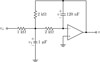
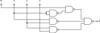
Here are a few examples of what I have made during my undegraduate years. More can be found in my Flickr page.


Technorati Tags: circuit_macros, tex, latex, typesetting, electronics, schematic diagrams, circuits